 |
HOW TO DRAW AN OBJECT IN 3D ? |
| INTRODUCTION |
This document presents a method to display objects in 3 dimensions. There are of course different ways to do that. The method presented here is certainly not the most efficient, but it appears to be quite easy to understand. We consider here that the 3D objects are simply formed of segments, the faces will be transparent. So this document is about representing the objects as "wireframed". This way of displaying objects in 3D is illustrated by the applet written in Java, for which the source code is available.
| Representation of an Object in 3D |
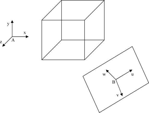
A 3D object is composed with points Pi of coordinates (xi;yi;zi) in the reference (A;x;y;z) that we will call the "absolute" reference. The coordinates of A are (xa;ya;za).
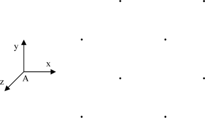
The points can be linked to form edges and describe the form of the object. We note Lij the line that links the point Pi to the point Pj.
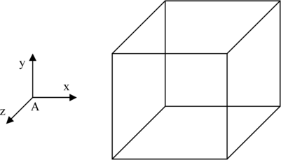
The points could be grouped to form faces with a color or a texture in order to give a more realistic aspect.
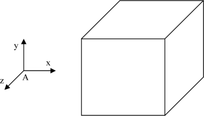
Here we limit ourselves to a "wireframed" representation. Hence, an object O = (P;L) is composed with a set of points P and a set of lines L.
| Display of an Object in 3D |
To display an object on a computer screen, we can use the following technique. We represent the computer screen as a reference (B;u;v;w). The point B of coordinates (xb;yb;zb) is the center of the screen; the vector u represents the horizontal direction of the screen, from the left to the right; the vector v represents the vertical direction of the screen, from the top to the bottom; and the vector w represents the direction of the glance of the observer, from the eye to the object.
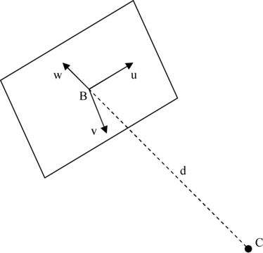
The observer is located in front of the screen. We consider that the eyes, represented by the point C of coordinates (xc;yc;zc), are just in front of the center B of the screen. Hence, the point B is on the axis (C;w) at a distance d from the screen.
The observation of an objet on the screen can be schematized by the following figure where beams of light are traced going from points of the object to the eye of the observer.
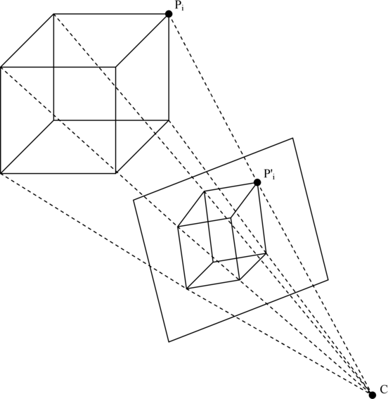
Here is the technique to represent the object. The points Pi of the object are projected on the screen to form the points P'i. To do so, we determine the segments [PiC] that start from the points Pi and arrive to the point C, the eye. Then, we just need to calculate the intersections P'i of the segments with the screen. Once the points are projected, we just have to draw the edges that form the object: for each line Lij, we must draw a line L'ij that links the point P'i to the point P'j.
We choose here to decompose the projection of the points of the object on the screen in two steps. The first stage consists in changing the reference of the points of the object. From the absolute reference (A;x;y;z), the points are expressed in the reference (B;u;v;w) of the screen. This step is detailed in the section "Reference Change". Then, the computing of the projection is performed (very simple once the reference is changed). This step is detailed in the section "Projection on the Screen".
| Movements in the 3D Scene |
Once we are able to display a 3D object, it can be interesting to see it under different angles. For that, the section "Movements in the 3D Scene" proposes different kinds of movement in the 3D space such as turn, move forward, go up...
| REFERENCE CHANGE |
We consider a point Pi of coordinates (xi,yi,zi) in the reference (A;x;y;z) and we try to determine its coordinates (ui;vi;wi) in the reference (B;u;v;w).
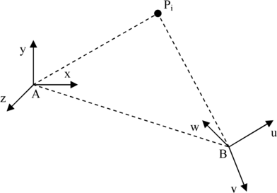
In the reference (A;x;y;z), we see that the vector APi has the coordinates (xi;yi;zi) and the vector AB has the coordinates (xb;yb;zb). In the reference (B;u;v;w), the vector BPi has the coordinates (ui,vi,wi). From the equality APi = AB + BPi and the previous observations, we deduce:
xi x + yi y + zi z = (xb x + yb y + zb z) + (ui u + vi v + wi w)
(xi - xb) x + (yi - yb) y + (zi - zb) z = ui u + vi v + wi w
By considering that the vectors u, v and w have respectively the coordinates (xu;yu;zu), (xv;yv;zv) and (xw;yw;zw), we deduce the following system of equations.
xi - xb = xuui + xvvi + xwwi
yi - yb = yuui + yvvi + ywwi
zi - zb = zuui + zvvi + zwwi
After resolution, we obtain:
ui = [(xi - xb) da1 + (yi - yb) da2 + (zi - zb) da3] / [xuda1 + yuda2 + zuda3]
vi = [(xi - xb) db1 + (yi - yb) db2 + (zi - zb) db3] / [xvdb1 + yvdb2 + zvdb3]
wi = [(xi - xb) dc1 + (yi - yb) dc2 + (zi - zb) dc3] / [xwdc1 + ywdc2 + zwdc3]
with:
da1 = yvzw - zvyw
da2 = zvxw - xvzw
da3 = xvyw - yvxwdb1 = ywzu - zwyu
db2 = zwxu - xwzu
db3 = xwyu - ywxudc1 = yuzv - zuyv
dc2 = zuxv - xuzv
dc3 = xuyv - yuxv
To calculate the coordinates (ui,vi,wi) of the points Pi of a 3D object in the screen reference, we just need to apply the previous formulas.
| PROJECTION ON THE SCREEN |
| Projection of the Points |
We consider a point Pi of the 3D object for which we know the coordinates (ui,vi,wi) in the screen reference. We try now to calculate the coordinates (u'i,v'i,w'i) of the projection P'i of Pi on the screen. We can already say that w'i = 0, because P'i is on the plane of the screen.
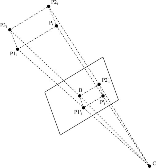
Now we must find the intersection of the straight line (PiC) with the plane of the screen (B;u;v). From the figure, we can say:
||P1'iB|| / ||P1iP3i|| = ||P2'iB|| / ||P2iP3i|| = ||BC|| / ||P3iC||
||x|| means the length of the segment x. We note r the ratio ||BC|| / ||P3iC||. We deduce:
r = d / (wi + d)
From the figure, we can say:
||P1'iB|| = v'i
||P2'iB|| = u'i
||P1iP3i|| = vi
||P2iP3i|| = ui
Which means that u'i = uir and v'i = vir. To resume, the coordinates of P'i are (uir;vir;0).
| Drawing of the Edges |
To draw the 3D object, we must draw the edges of the object one after the other. We consider one of these lines Lij from the point Pi to the point Pj. Three cases can appear.
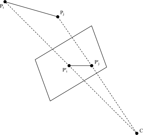
| Case 1: The line is in front of the screen |
In this case, we only need to draw a line on the screen from the projection P'i of Pi to the projection P'j of Pj.
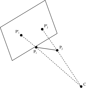
| Case 2: The line is behind the screen |
In this case, no part of the line is supposed to be seen by the observer, so we do not draw any line.
| Case 3: The line intersects the screen |
In this case, one of the points is in front of the screen, we suppose Pi, and the other one is behind the screen, we suppose Pj. To draw the part of the line that the observer is supposed to see, we must determine the intersection P''j of the straight line (PiPj) with the screen. Then, we just have to draw the line (P'iP''j).
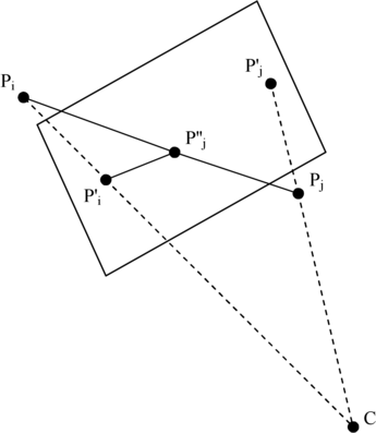
To calculate the coordinates (u''i;v''i;w''i) of P''j, we use the same technique as with the projection. We determine the ratio r = wi / (wi - wj) that allows us to calculate the coordinates:
u''j = ui + (uj - ui) r
v''j = vj + (vj - vi) r
w''j = 0
| MOVEMENTS IN THE 3D SCENE |
Now that we are able to project a 3D object on the computer screen, it can be interesting to move in the 3D scene in order to see the object under different angles. Of course, when we "move", that is in fact the screen that changes its position and/or its orientation with regard to the object. Here is the list of the few movements proposed here (sorted from the simplest to the most complicated).
Translations of the screen (right / left, up / down, forward / backward).
Rotations of the screen around its central point (right / left, up / down, inclination right / left).
Rotations around a point of the scene (right / left, up / down).
| Translations of the Screen |
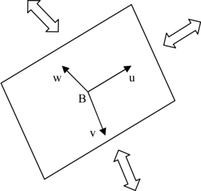
These translations consist in moving the screen along one of the three directions u, v or w of a given distance k.
| Translation Right / Left |
To move the screen to the right, we must translate its center B along u in the positive direction.
B ← B + k u ⇔ xb ← xb + kxu
yb ← yb + kyu
zb ← zb + kzu
To move the screen to the left, we must translate its center B along u in the negative direction.
B ← B - k u
| Translation Up / Down |
To move the screen up, we must translate its center B along v in the negative direction.
B ← B - k v
To move the screen down, we must translate its center B along v in the positive direction.
B ← B + k v
| Translation Forward / Backward |
To move the screen forward, we must translate its center B along w in the positive direction.
B ← B + k w
To move the screen backward, we must translate its center B along w in the negative direction.
B ← B - k w
| Rotations of the Screen |
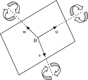
These rotations consist in turning the screen around one of the three axis (B;u), (B;v) or (B;w) of a given angle k.
| Rotation Right |
To turn the screen on the right, we must perform a positive rotation around the axis (B;v). For that, we only have to consider the plane (B,u,w) and to modify the coordinates of the vectors u and w in order that they perform the rotation.
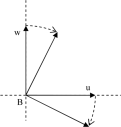
From the figure, this rotation is expressed:
u ← u cos(k) - w sin(k) ⇔ xu ← xu cos(k) - xw sin(k)
yu ← yu cos(k) - yw sin(k)
zu ← zu cos(k) - zw sin(k)w ← w cos(k) + u sin(k) ⇔ xw ← xw cos(k) + xu sin(k)
yw ← yw cos(k) + yu sin(k)
zw ← zw cos(k) + zu sin(k)
However, u and v must still with the length 1. Because of the rounding during the computing, their length will decrease progressively, rotation after rotation. To avoid that, we must adjust to 1 the length of the vectors (i.e. normalize the vectors). Very simply, we calculate the length d of the vector (for instance v).
d = √(xv2 + yv2 + zv2)
Then, we normalize the vector.
v ← v / d ⇔ xv ← xv / d
yv ← yv / d
zv ← zv / d
Remark: Due to the normalization, the rotation can be done more easily with the help of the tangent.
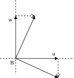
From the figure, the rotation can finally be expressed:
u' ← u - w tan(k) ⇔ xu' ← xu - xw tan(k)
yu' ← yu - yw tan(k)
zu' ← zu - zw tan(k)w' ← w + u tan(k) ⇔ xw' ← xw + xu tan(k)
yw' ← yw + yu tan(k)
zw' ← zw + zu tan(k)u ← u' / ||u'|| w ← w' / ||w'||
| Rotation Left |
To turn the screen on the left, we must perform a negative rotation around the axis (B;v).
u' ← u + w tan(k)
w' ← w - u tan(k)
u ← u' / ||u'||
w ← w' / ||w'||
| Rotation Up / Down |
To turn the screen up, we must perform a positive rotation around the axis (B;u).
w' ← w - v tan(k)
v' ← v + w tan(k)
w ← w' / ||w'||
v ← v' / ||v'||
To turn the screen down, we must perform a negative rotation around the axis (B;u).
w' ← w + v tan(k)
v' ← v - w tan(k)
w ← w' / ||w'||
v ← v' / ||v'||
| Inclination Right / Left |
To incline the screen on the right, we must perform a positive rotation around the axis (B;w).
v' ← v - u tan(k)
u' ← u + v tan(k)
v ← v' / ||v'||
u ← u' / ||u'||
To incline the screen on the left, we must perform a negative rotation around the axis (B;w).
v' ← v + u tan(k)
u' ← u - v tan(k)
v ← v' / ||v'||
u ← u' / ||u'||
| Rotations Around a Point of the Scene |
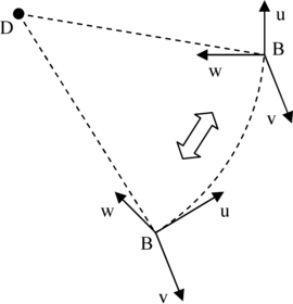
These rotations consist in turning of an angle k in one of the three planes (B;u;w), (B;v;w) and (B;v;u) around a given point D. The rotation is such as the location on the screen of the point D has not changed. That comes to turn around an object while always looking at the same point (here it is D). Hence, if we choose D as the center of a 3D object, we have the illusion that this is the object that turns on itself and not the observer that moves.
| Central Rotation Right |
To turn on the right around the point D, we first need to perform a positive rotation of angle k of the center B around the projection D' of the point D on the plane (B;u;w).
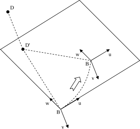
Then, we just have to perform a left rotation of the screen of the same angle k (we will use the "rotation left" seen previously).
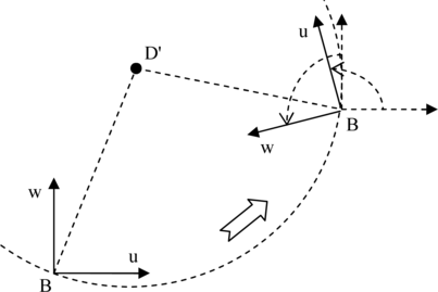
First, the coordinates (ud;vd;wd) of the point D are calculated in the reference (B;u;v;w) (with the formula presented in the section on the reference change). Hence, the coordinates of the projection D' of the point D on the plane (B;u;w) are (ud;0;wd). The distance d1 = ||BD'|| is also calculated. It will intervene later in order to guarantee that the distance ||BD'|| stills unchanged once the rotation is terminated.
The central rotation begins with a rotation of the point B around D' in the plane (B;u;w) by using the technique of the tangent seen before.
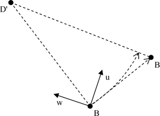
From the figure, the point B is translated along a vector perpendicular to BD' for which the coordinates in the plane (B;u;w) are (wd;-ud). To respect the rotation angle k, B is translated the following way.
B ← B + u wd tan(k) - v ud tan(k)
Then, the segment [BD'] is brought back to its old length (i.e. d1). To do so, we calculate d2, the new distance of [BD'], and we determine the ratio r = (d2 - d1) / d2. We just need then to translate B of the vector r BD'. To simplify the computation, the new coordinates of D' in the reference (B;u;v;w) can be calculated. Hence, the translation is expressed:
B ← B + r BD' ⇔ B ← B + u r ud + w r wd
Then, we must turn the screen to put it back in the good direction. To do so, we only have to apply the operation "rotation left" seen previously with the angle k.
| Central Rotation Left |
To turn on the left around the point D, we first need to perform a negative rotation of angle k of the center B around the projection D' of the point D on the plane (B;u;w). Then, we just have to perform a right rotation of the screen of the same angle k (we will use the "rotation right" seen previously).
| Central Rotation Up |
To turn up around the point D, we first need to perform a negative rotation of angle k of the center B around the projection D' of the point D on the plane (B;v;w). Then, we just have to perform a down rotation of the screen of the same angle k (we will use the "rotation down" seen previously).
| Central Rotation Down |
To turn down around the point D, we first need to perform a positive rotation of angle k of the center B around the projection D' of the point D on the plane (B;v;w). Then, we just have to perform an up rotation of the screen of the same angle k (we will use the "rotation up" seen previously).